single page feature image

    Project Details

  • Category:
  • Client: Henry Ford CEH Building
  • Location: Campus of Henry Ford Hospital 2799 West Grand BoulevardDetroit, Michigan 48202

    Contact Info

  • Canada Corner Nashik
  • 91 982 3191 442
  • kothekar@ananataaccess.in

Henry Ford CEH Building

About Project

Fabricator Name : Sarnia based Fabricator. ON. CAN
GC : IDEAL Contracting
Construction: IDEAL Contracting
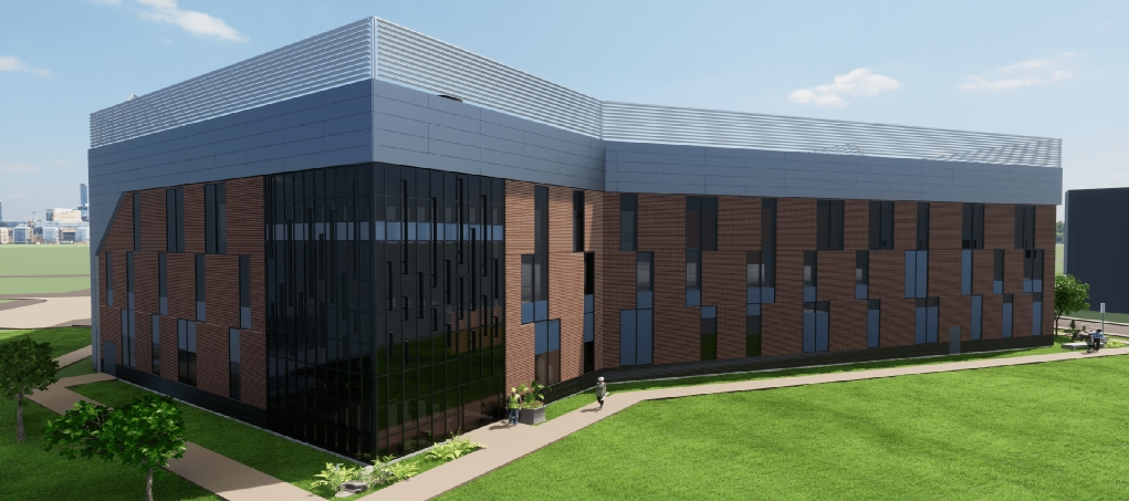
Project Name : Henry Ford CEH Building Central Energy Hub
Project Type : Commercial Building
Tonnage : 700 T
Project Duration : 08Months
Team Size : 14

Project Deliverables:

  • 3D Model Development: Comprehensive 3D model created based
    on the received design drawings.
  • Member-Level Fabrication Drawings: Detailed shop drawings for each structural member, including bill of materials.
  • Assembly Part Details: Separate fabrication details for assembly
    components such as plates, angles, channels, etc.
  • Field Erection Drawings: Clear and coordinated erection drawings
    for on-site installation.
  • Procurement & Coordination Files: EJE, KISS files, material summaries, bolt lists, and other procurement-related documentation as per client specifications.
  • Customized Reports: Generation of client-specific reports including CNC files, DXF plates, Fabtrol exports, and more.

Challenges in projects:

  • Project Scope & Complexity: The project encompassed approximately 34 sequences, including miscellaneous steel components with intricate framing. Managing coordination across these sequences posed significant challenges.
  • Interdisciplinary Collaboration: Close coordination was required with architects, MEP (Mechanical, Electrical, and Plumbing) engineers, and other stakeholders to ensure seamless integration of structural elements into the overall design.
  • Diverse Surface Treatments: The project involved a variety of surface preparation and finishing techniques to meet structural and client specifications—ranging from galvanization and color galvanization to fireproof coatings and safety paints.
  • Structural Connectivity & Load Management: Implementation of various connection strategies for heavy structural members spanning long lengths, tailored to meet specific load-bearing requirements.
  • Design Adaptability: Responsive design adjustments were made throughout the project to accommodate revisions and client feedback- without compromising structural integrity or delivery schedules.
  • The roof steel horizontal bracing consists of WT sections with bolted connections at both ends of the top flanges, in accordance with detailed design calculations. Located within a designated loading zone, this bracing system supports the generator support framing, while multiple pipe support assembly frames are located beneath the cooling tower support framing.
  • Stair 101-S features concrete-filled pan treads, providing enhanced durability and slip resistance. The stair stringers and handrails were fully shop-assembled, ensuring precision and efficiency during installation. A cane rail is integrated below the handrail, with guardrails positioned at the top of the stair for added safety. The design includes an intermediate
    landing, supported by a structural steel frame for stability and load distribution.
  • Included various assemblies such as safety rails, access ladders, and grated platforms to support functionality and compliance. In addition, protective bollards and access control gates were installed to enhance site safety and secure designated areas.
  • Stair 501-S was constructed with open grating treads, offering durability and drainage in industrial settings. The stair stringers and handrails were provided as fully fabricated individual assemblies for efficient on-site installation. A cane rail was installed below the handrail, with guardrails at the top of the stair to ensure safety and code compliance. Both intermediate and top landings were also designed using grating, maintaining consistency and functionality throughout the system.
  • Sequence 601 comprises the generator support framing, while Sequence 701 includes the cooling tower support framing. Both assemblies feature a painted galvanized finish for enhanced durability and corrosion resistance. The scope includes a wide range of structural elements such as pipe supports, horizontal bracing, stairs, handrails, and grating platforms, all integrated to meet functional and safety requirements.
  • The platform features multiple landings equipped with grating stairs, handrails, and grated flooring for safe and efficient access. Removable railings were incorporated to allow flexibility for maintenance and equipment handling. All components were finished with a painted galvanized coating, ensuring long-term protection against corrosion and environmentl exposure.


Achievements

  • Successfully secured project approvals several months ahead of the originally scheduled deadlines, demonstrating proactive planning, efficient execution, and strong coordination across teams.
  • Delivered a flawless finish with zero issues reported related to paintwork,
    electrical connections, or other detailing aspects —ensuring a smooth handover.
  • Resulted in a highly satisfied and appreciative customer, reflecting our
    commitment to quality and excellence in execution.